HW place
Something from my hardware
- Hits: 605
10W spínaný zdroj // 10W switch mode power supply
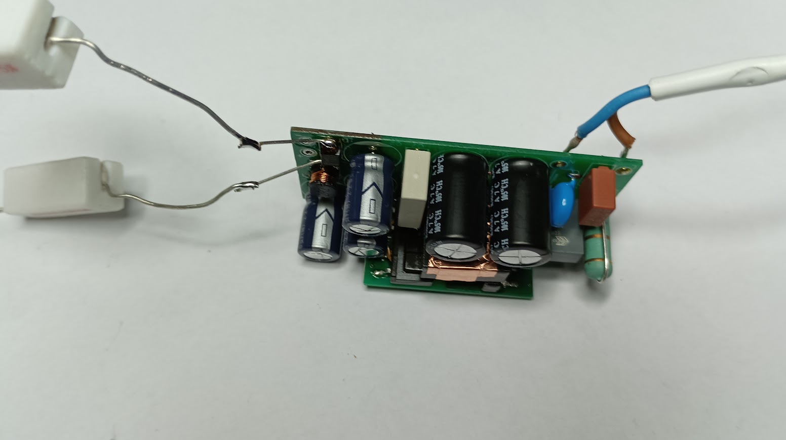
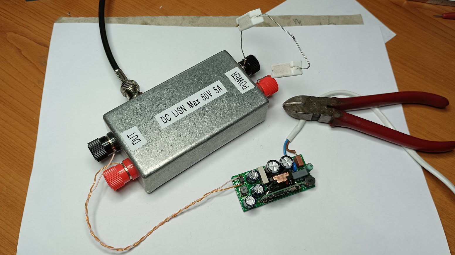
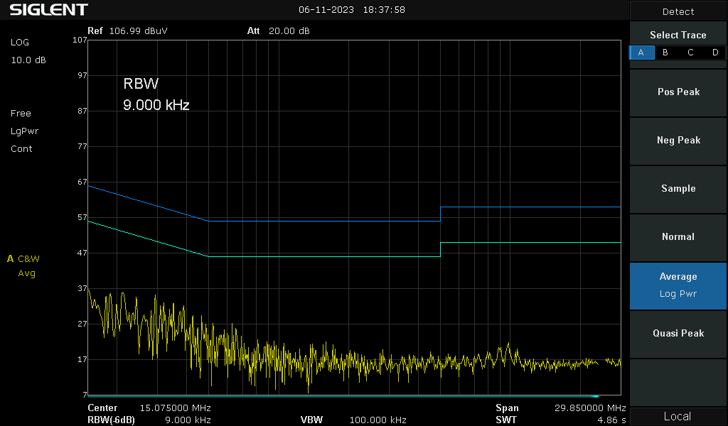
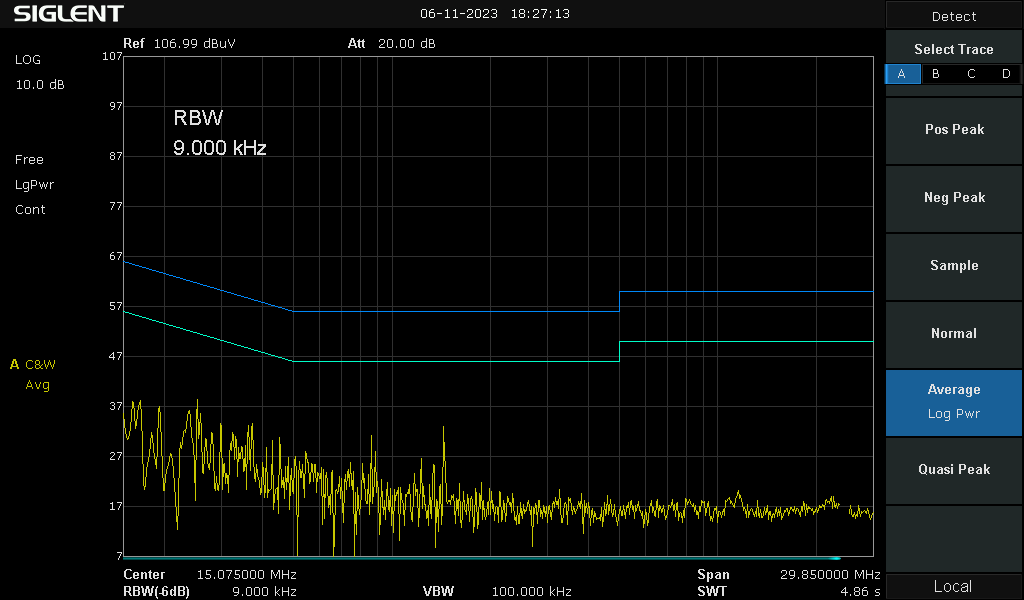
CZ Pro napájení různých zařízení v domácnosti se dnes prakticky výhradně používají malé spínané zdroje v podobě adaptéru do zásuvky. Tyto adaptéry mají různou kvalitu zpracování a ve většině případů nejen, že mají velmi vysoké vyzařování v oblasti krátkých vln, ale díky ošizené konstrukci jsou i nebezpečné. V našem domě tak za poslední roky přibyla různá zařízení, které nesplňují normy na EMC, nebo jsou těsně pod limitem a bohužel moje antény na KV ve spojení s citlivým přijímačem většinu tohoto rušení přijímají. Vznikl tak tento univerzální napájecí zdroj 10W, který lze snadno zhotovit s opakovatelným výsledkem, velmi nízkým vyzařováním a splňující bezpečnostní požadavky. Jako základ byl použit modul LS10 od firmy Mornsun a zapojen dle doporučeného zapojení. Ohled byl brán zejména na nízké rušení. Výsledek se dostavil po laborování s komponenty a drobnými úpravami plošného spoje. Výsledkem je malý plošný spoj, na kterém je uvedený modul a několik málo komponent. Obrázky níže pro inspiraci včetně měření vyzařování do vedení. Do příštích aplikací by bylo vhodné zakomponovat lepší vstupní filtr, ale i takto by zdroj měl bez problému projít na EMC ve zkušebně. Velikost plošného spoje je volena velmi malá proto, aby se celý zdroj vešel do originální krabičky. Osazení a kompletace zdroje zabere jen několik desítek minut.
EN Today, small switching power supplies in the form of a wall adapter are almost exclusively used to power various household devices. These adapters are of varying workmanship and in most cases not only have very high radiation in the short wave bands, but are also dangerous due to their shoddy construction. Thus, our house has over the years added various devices that do not meet EMC standards or are just below the limit and unfortunately my KV antennas in conjunction with a sensitive receiver receive most of this interference. Thus this universal 10W power supply was created which is easy to make with repeatable results, very low radiation and meets safety requirements. The LS10 module from Mornsun was used as a base and connected as recommended. Particular attention was paid to low EMI. The result came after tinkering with components and minor modifications to the PCB. The result is a small PCB with the module and a few components. See the pictures below for inspiration, including measurements of EMI into the wiring. For future applications, it would be advisable to incorporate a better input filter, but even this way the source should pass the EMC without any problem. The PCB size is chosen to be very small so that the entire power supply fits into the original box. It takes only a few tens of minutes to install and assemble the power supply.
Schematic diagram
PCB

Power supply during the test
Side view

Bottom view
During emission measurement on the output
Emission at DC output
Emission to AC power line
Bill of material from ECOM www.ecom.cz
- Hits: 1027
GPSDO - GPS disciplined oscillator
CZ Pro přesné měření kmitočtu a zdroj kvalitního hodinového signálu pro přístroje v oblasti VF techniky je potřebný kvalitní a přesný zdroj kmitočtu. Do současné doby používaný krystalový oscilátor bez stabilizace kmitočtu mi již přestal vyhovovat a krok k teplotně stabilizovanému oscilátoru by sice přinesl dosti velké zlepšení, ale oscilátory řízené GPS dosahuji skok do úplně jiné dimenze. Po prohlížení různých konstrukcí na webu jsem nakonec zvolil projekt podle Yannick Turcotte na webu Instructables. Tato konstrukce je velmi hezky popsaná a dosažené výsledky jsou nad můj stanovený cíl. Velká část konstrukce je převzata od uvedeného autora (odkaz na konci tohoto příspěvku) a dále přizpůsobena mým požadavkům.
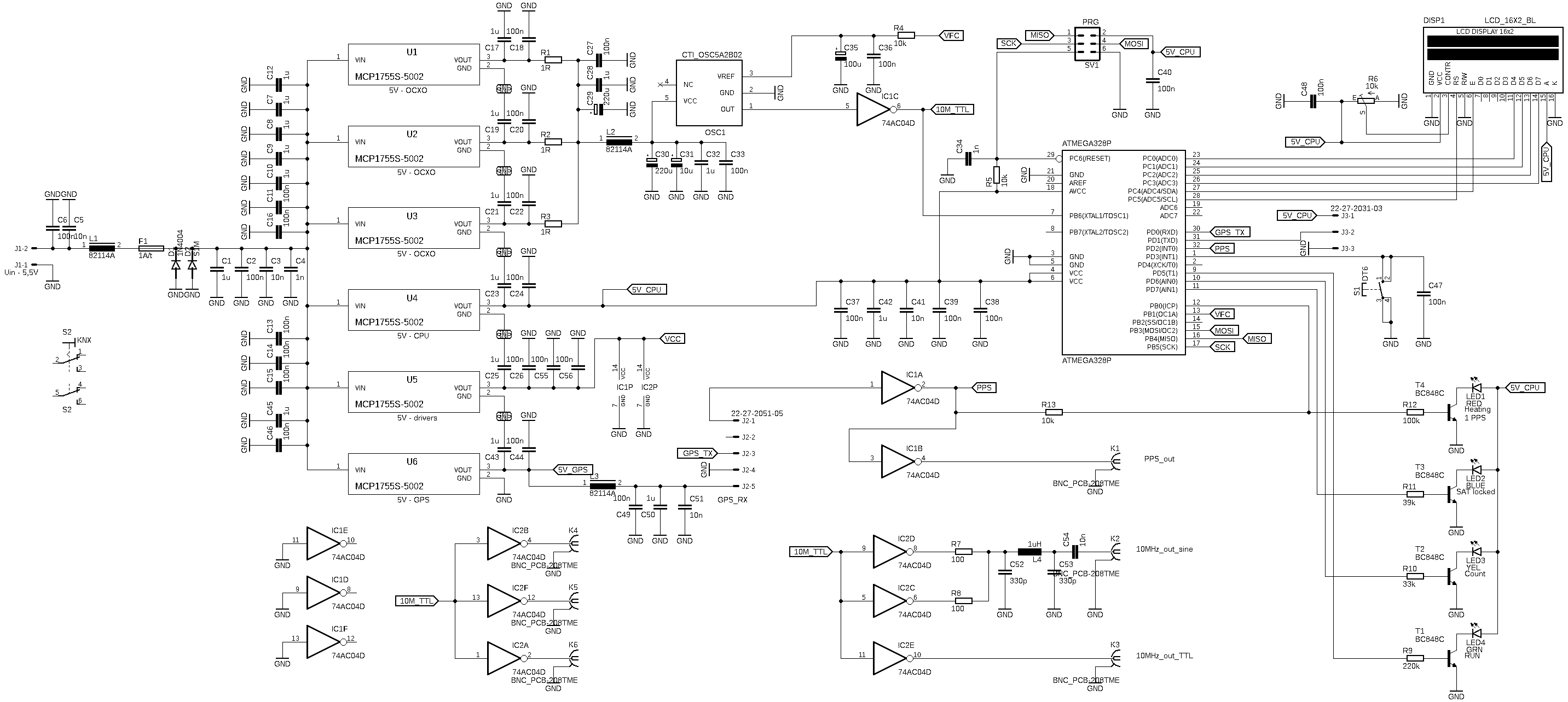
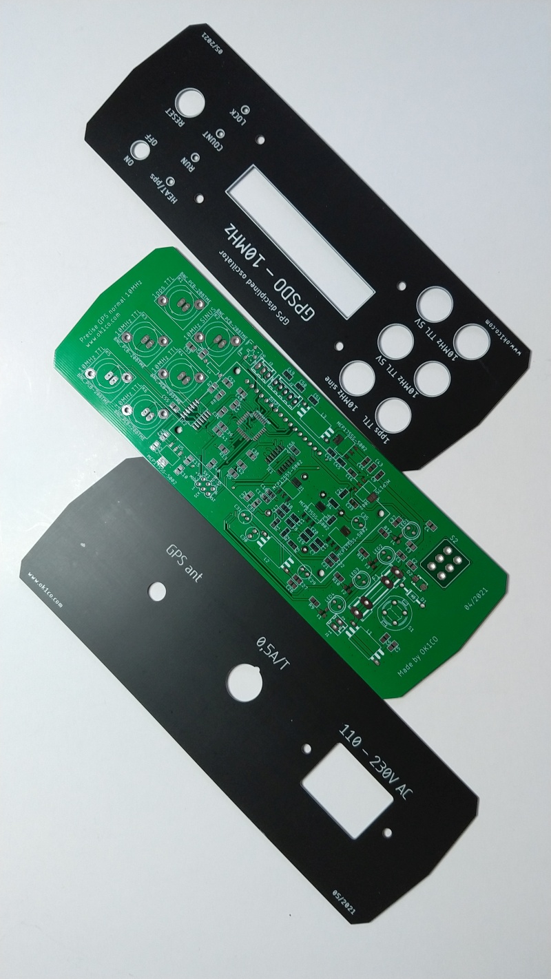
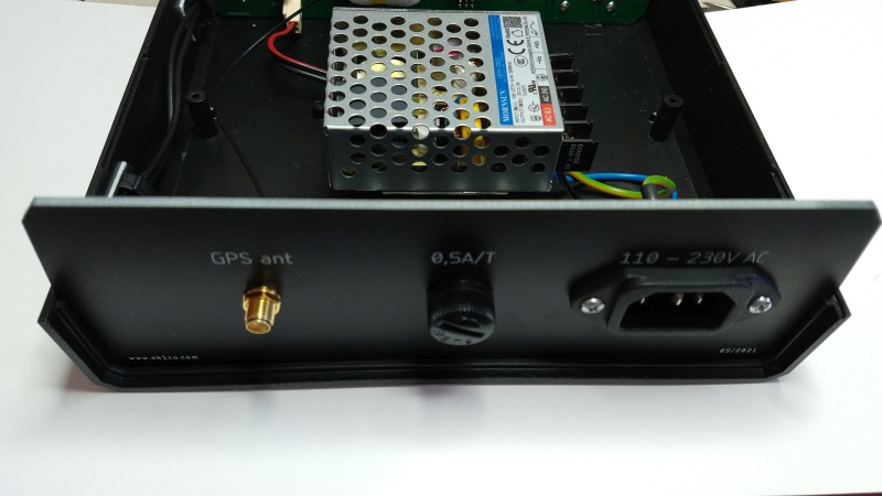
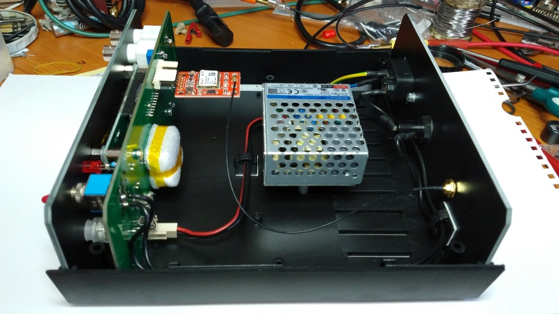
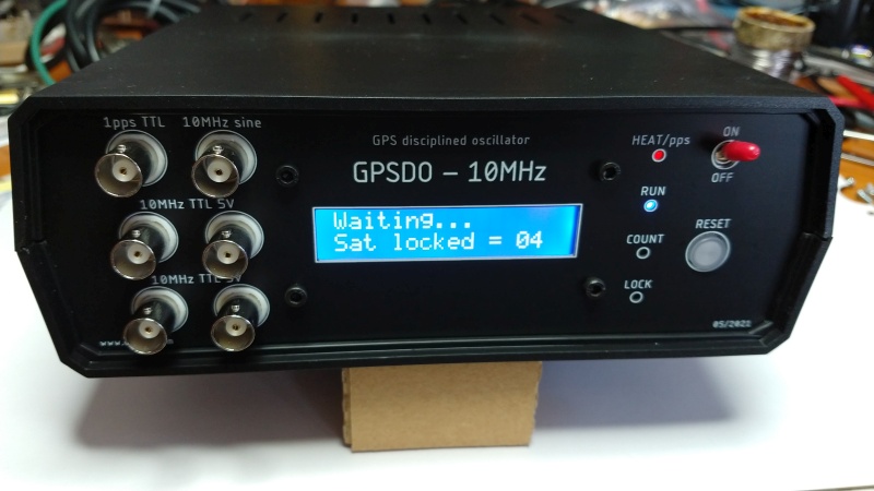
Srdcem celého GPSDO je temperovaný krystalový oscilátor (OCXO) 10MHz, procesor ATMEGA328 a GPS modul. Po zapnutí tedy probíhá 15 minut temperování oscilátoru a poté je porovnáván počet pulsů oscilátoru 10MHz za periody 10, 60, 200 a 1000 sekund. Pro přesné odečítání jednotlivých period je použit signál PPS 1Hz z modulu GPS. V těchto periodách je oscilátor korigován až je dosaženo konečné přesnosti 1mHz při 10MHz. Přesnost je to úchvatná a porovnáme-li to s něčím jiným, je to jako měřit vzdálenost 10.000km s přesností 1mm. Schéma i výkres plošného spoje je níže, včetně několika fotografií. GPSDO je umístěn do plastové krabice. Plošný spoj, čelní a zadní panel je vyroben z kuprextitu a opatřen potiskem. Součástí je také napájecí zdroj 15W, který celý GPSDO napájí. Pro příjem GPS signálu je vhodné umístit anténu alespoň za okno, s GPS modulem běžně přijímám 5-10 satelitů současně. Kdo by chtěl dosáhnout ještě vyšší stability, stálo by za úvahu použit GNSS modul s velmi nízkým jitterem. Testoval jsem několik různých modulů, kde byl jitter PPS signálu obvykle kolem 20ns, modul MC-1722-T dosahuje obvykle jitter jen 2ns (max. 5ns), pro 5G sítě je limit 10ns. Další podrobnosti jsou patrné z obrázků níže.
EN For accurate frequency measurement and a quality clock signal source for instruments in RF technology, a quality and accurate frequency source is required. The crystal oscillator without frequency stabilization that has been used to date is no longer satisfactory to me, and a move to a temperature stabilized oscillator would indeed bring quite an improvement, but GPS controlled oscillators achieve a leap into a whole other dimension. After looking at various designs on the web, I finally chose a design by Yannick Turcotte on the Instructables site. This design is very nicely described and the results achieved are beyond my stated goal. A large part of the design is taken from that author (link at the end of this post) and further adapted to my requirements.
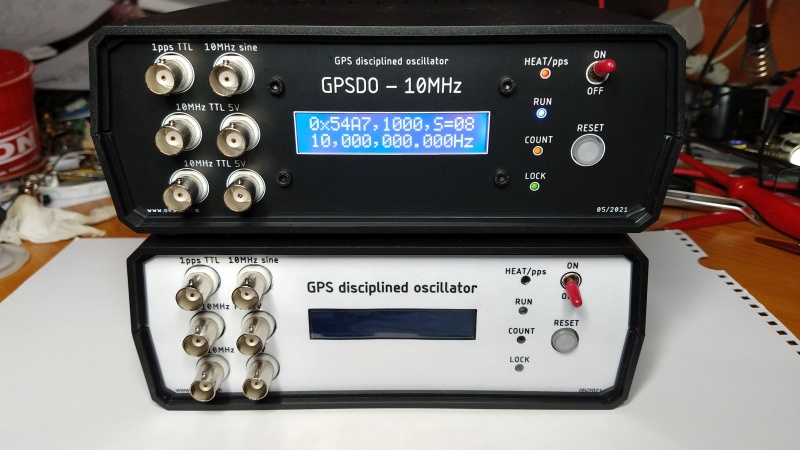
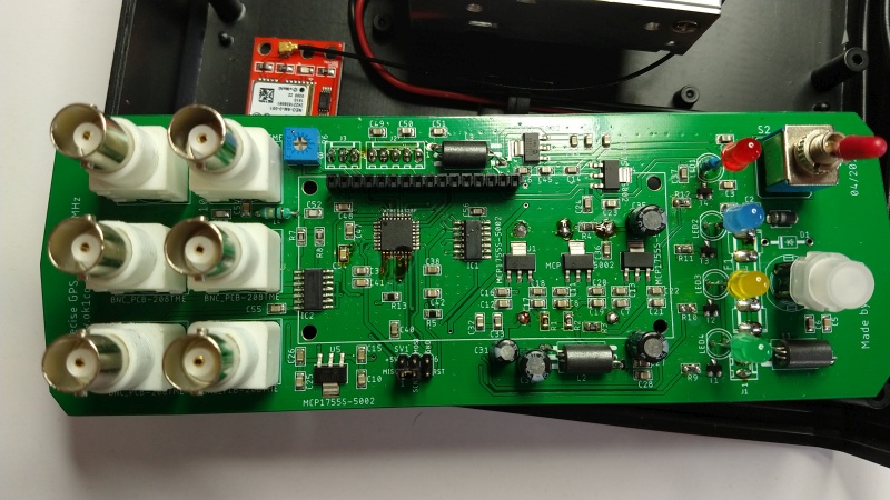
The heart of the GPSDO is a 10MHz oven controlled crystal oscillator (OCXO), an ATMEGA328 processor and a GPS module. So, after power-up, the oscillator is tempered for 15 minutes and then the number of pulses of the 10MHz oscillator is compared for periods of 10, 60, 200 and 1000 seconds. The 1Hz PPS signal from the GPS module is used for accurate period readings. During these periods the oscillator is corrected until a final accuracy of 1mHz at 10MHz is achieved. The accuracy is breathtaking and if you compare it to anything else, it's like measuring a distance of 10,000km with an accuracy of 1mm. A schematic and drawing of the PCB is below, including some photos. The GPSDO is housed in a plastic box. The PCB, front and back panels are made of cuprextite and printed symbols for panels. Also included is a 15W power supply that powers the entire GPSDO. For GPS signal reception it is advisable to place the antenna at least outside the window, with the GPS module I normally receive 5-10 satellites at the same time. If you would like to achieve even higher stability, it would be worth considering using a GNSS module with very low jitter. I tested several different modules where the PPS signal jitter was usually around 20ns, the MC-1722-T module from Locosys usually reaches a jitter of only 2ns (max 5ns), for 5G networks the limit is 10ns. Further details can be seen in the images below.
Schematic diagram
PCB
New and old GSPDO
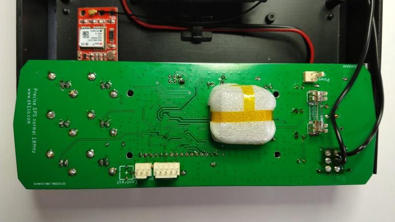
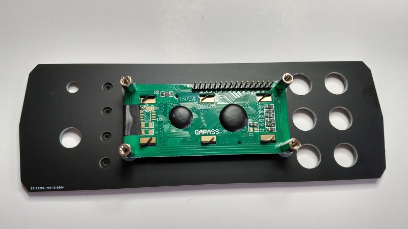
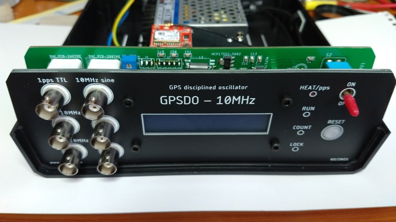
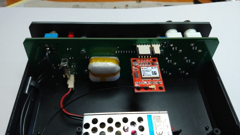
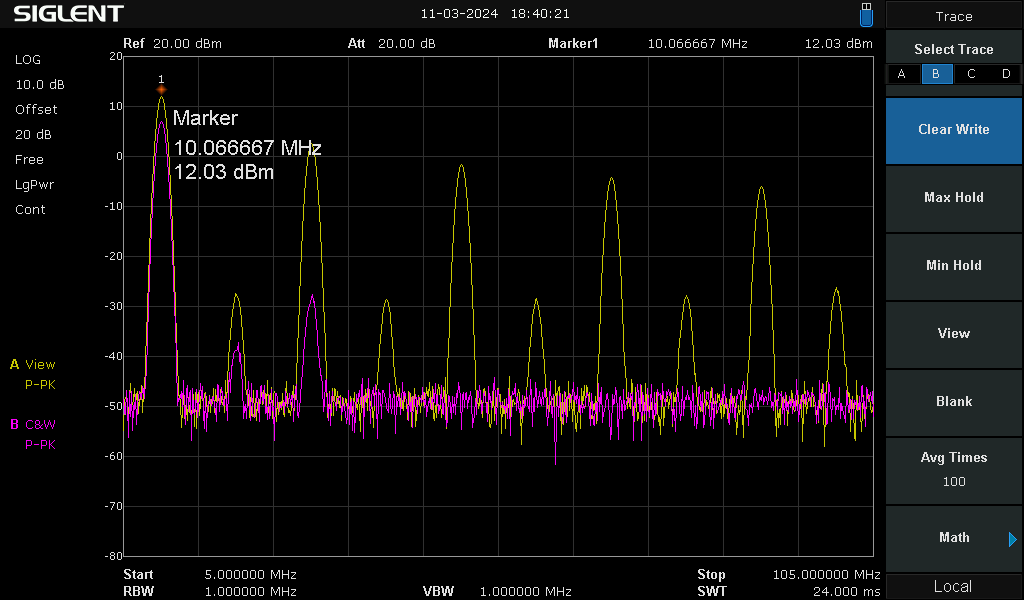
Output spectrum - Yellow TTL output and Pink sinus output
Source :
- Hits: 589
Izolátor pro ethernet 100Mbit // Ethernet isolator 100Mbit
CZ V domácnosti máme většinu datových rozvodů pomocí ethernetových stíněných kabelů. Vyzařování těchto kabelů je sice nízké, kabely díky svojí konstrukci a stínění mají velmi dobré vlastnosti, ale i přesto může rušení vyzařováním způsobovat problém při poslechu na krátkých vlnách, případně absorbovat energii z vysílače a ovlivnit tak funkci zařízení. Při radioamatérském vysílání, kdy tyto kabely nejsou daleko od antén je vzájemná možnost ovlivnění velmi vysoká. Dále je možnost vzniku zemních smyček vlivem různých propojovacích cest, což je opět zdroj mnoha rušení, která se velmi špatně vyhledávají a odstraňují. Z uvedených důvodů jsem se rozhodl tyto kabely vzájemně oddělit galvanickou izolací. Pro tento účel se velmi hodí konektory RJ45 s interními transformátory a kompenzovanými tlumivkami na vedení. Vzal jsem tedy dva uvedené konektory a propojil jsem je proti sobě pájecími piny. Oba spojené konektory jsem umístil do smršťovací bužírky pro základní mechanickou ochranu. Vznikl tak velmi jednoduchý kompaktní modul, který lze zapojit jako spojku do ethernetového kabelu. Díky jednoduché konstrukci jsou náklady na stavbu minimální s vysokou efektivitou. Zatím jsem měl k dispozici pouze konektory s integrovanými transformátory pro 100Mb (zapojeny pouze 2 páry vodičů), výhledově mám v plánu toto řešit již jako 1Gb (propojení 4 párů vodičů).
EN In our home, we have most of our data distribution using Ethernet shielded cables. Although the radiation of these cables is low, and the cables have very good properties due to their construction and shielding, radiation interference can still cause problems when listening at short waves, or absorb energy from the transmitter and affect the operation of the equipment. In amateur radio transmissions, where these cables are not far from the antennas, the potential for mutual interference is very high. There is also the possibility of ground loops due to various interconnection paths, which again is a source of many interferences that are very difficult to find and eliminate. For these reasons I decided to separate the cables by galvanic isolation. RJ45 connectors with internal transformers and compensated chokes on the wiring are very suitable for this purpose. So I took the two connectors mentioned above and connected them against each other with solder pins. I placed the two connected connectors in a shrink tube for basic mechanical protection. This created a very simple compact module that can be plugged into an Ethernet cable as a coupler. The simple design makes construction costs minimal with high efficiency. So far I only had connectors with integrated transformers for 100Mb (only 2 pairs of twisted wires connected), prospectively I plan to solve this as 1Gb (connecting 4 pairs of twisted wires).
Isolator during measurement on spectrum analyser
Common mode rejection
2023-10-24
- Hits: 576
Izolátor pro ethernet 1Gbit // Ethernet isolator 1Gbit
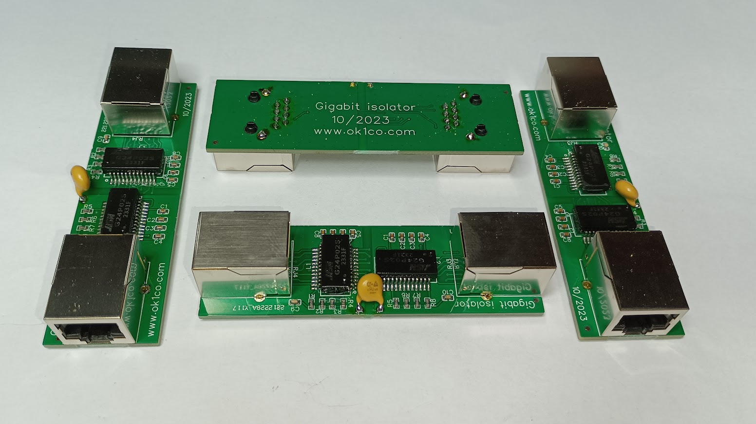
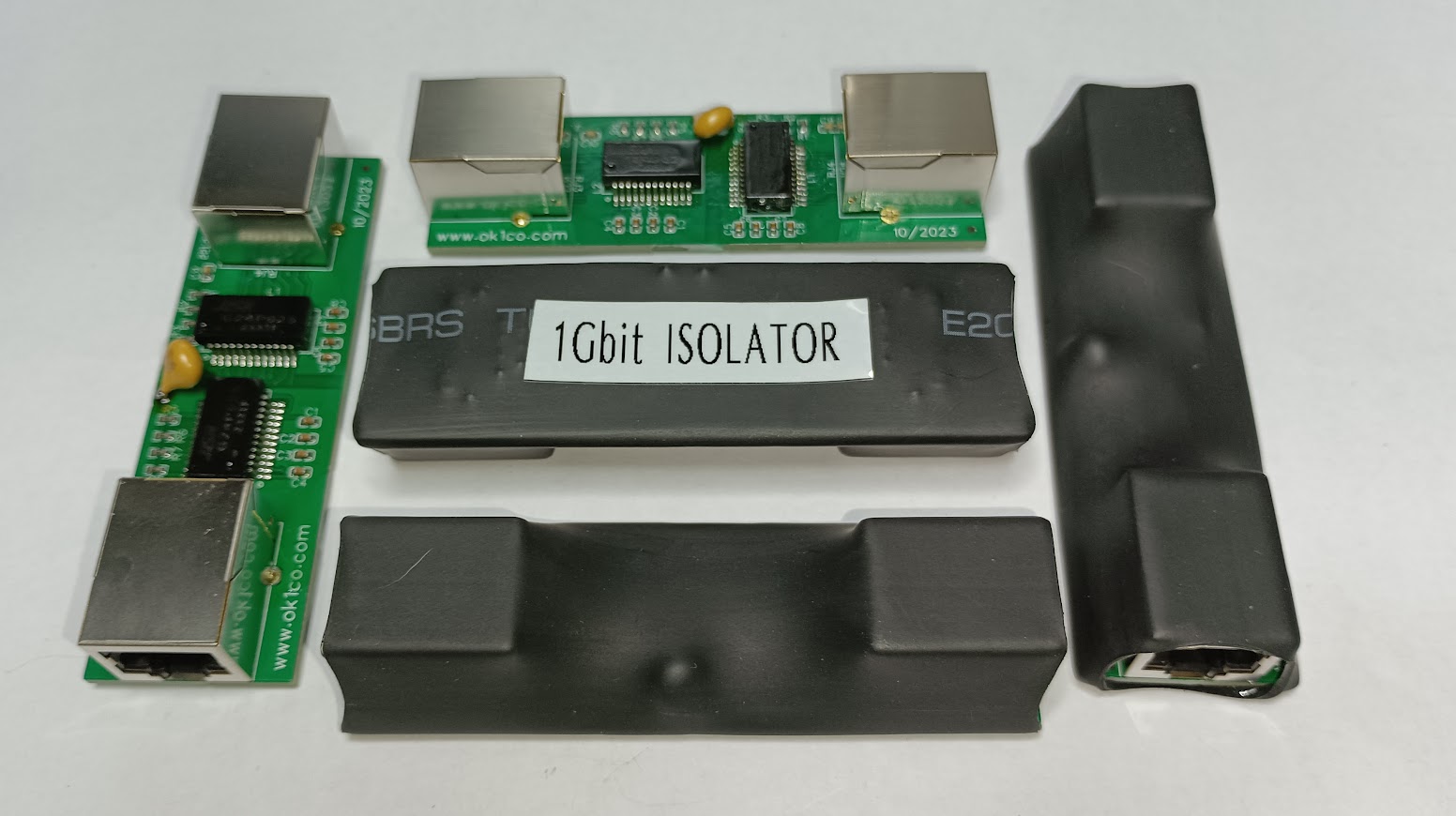
CZ V domácnosti máme většinu datových rozvodů pomocí ethernetových stíněných kabelů. Vyzařování těchto kabelů je sice nízké, kabely díky svojí konstrukci a stínění mají velmi dobré vlastnosti, ale i přesto může rušení vyzařováním způsobovat problém při poslechu na krátkých vlnách, případně absorbovat energii z vysílače a ovlivnit tak funkci zařízení. Při radioamatérském vysílání, kdy tyto kabely nejsou daleko od antén je vzájemná možnost ovlivnění velmi vysoká. Dále je možnost vzniku zemních smyček vlivem různých propojovacích cest, což je opět zdroj mnoha rušení, která se velmi špatně vyhledávají a odstraňují. Z uvedených důvodů jsem se rozhodl tyto kabely vzájemně oddělit galvanickou izolací. Již dříve jsem testoval izolátor pro 100Mbit, ale domácí síť mám konstruovanou pro rychlost 1Gbit, sice většina zařízení nevyužívá tuto rychlost, ale pro některá zařízení potřebuji (například pro rychlost kopírování) připojení 1Gbit. Navrhl jsem tedy tuto variantu, kdy jsem původně chtěl propojit je dva konektory s integrovaným oddělením, ale jejich cena je dost vysoká. Vzniklo tedy řešení s využitím levných oddělovacích transformátorů pro 1Gbit a konektorů samostatně a cena celého oddělovače se dostala na pětinu ceny. Výsledek je malý plošný spoj s oddělovači a konektory. Více napoví obrázky. Izolace v celém pásmu KV je více jak 20dB.
EN In our home, we have most of our data distribution using Ethernet shielded cables. Although the radiation from these cables is low, and the cables have very good properties due to their construction and shielding, interference from radiation can still cause problems when listening at short waves, or absorb energy from the transmitter and affect the operation of the equipment. In amateur radio transmissions, where these cables are not far from the antennas, the potential for mutual interference is very high. There is also the possibility of ground loops due to various interconnection paths, which again is a source of many interferences that are very difficult to find and eliminate. For these reasons I decided to separate the cables by galvanic isolation. I have previously tested an isolator for 100Mbit, but my home network is designed for 1Gbit speed, and although most devices do not use this speed, I do need a 1Gbit connection for some devices (for copy speed for example). So I proposed this option, where I originally wanted to connect them with two connectors with integrated separation, but their price is quite high. So a solution was created using cheap decoupling transformers for 1Gbit and the connectors separately, and the price of the whole isolator came to a fifth of the price. The result is a small PCB with isolator and connectors. The pictures will give more hints. Isolation on all HF bands is more than 20dB.
- Hits: 3791
Antenna switching - controller
In spring 2019 I broke my finger on left hand and I can't switching antenna with my mechanical switching, for this I developed electronics switching controller with microcontroller ATMEGA328P, with many buttons, LEDs, relays and controller. Now I can switch all my antenna between three transceiver and chose the right one. Down you can see few pictures of this controller.
All configuration are stored all the time, and after power on I can use previous configuration. From controller I can switch all remote relay switch by antenna position. Please see also my topic "Principle of antenna switching". I tested this controller during contests and OL700CO operation, it's very good help for antenna switching. Complete controller use 4 PCB with electronics, and from another two PCB I made front and rear panel.
I still have few PCBs for sale - if you have interes, contact me please.

Front panel without button

Rear panel without connectors

New controller and old mechanical controller

Output relays PCBs


Assembled front panel

New and old controller

New controller during operation


